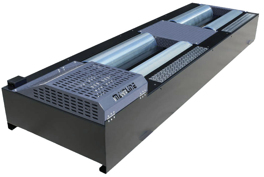
Chassis Dynamometer
A chassis dynamometer is an indoor bench testing device used to test a vehicle's power performance, emissions under various operating conditions, and fuel efficiency. The chassis dynamometer uses rollers to simulate a road surface, calculates road simulation equations, and uses a loading device to simulate the road, achieving accurate simulation of various vehicle operating conditions. It can be used for vehicle loading and adjustment, and to diagnose faults that occur under load conditions. Together with a five-gas analyzer,transmission smoke meter, engine tachometer, and computer-controlled system, it forms a comprehensive measurement system to measure vehicle exhaust emissions under different operating conditions.
A The chassis dynamometer is easy to use, reliable, and unaffected by external conditions. Without disassembling the vehicle, it can accurately and quickly test the performance of various systems and components. The chassis dynamometer can be used for scientific automotive testing and maintenance inspection.
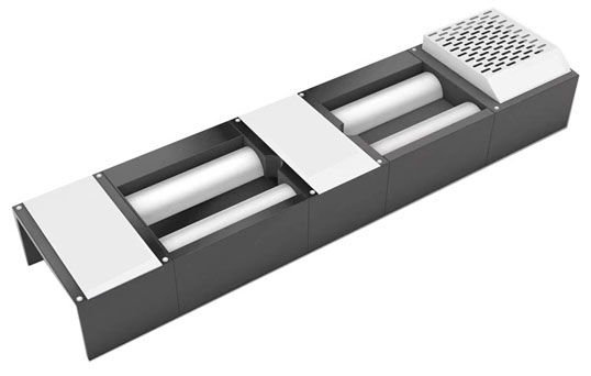
Basic Functions :
- Vehicle Speedometer Calibration Test
- Odometer Calibration Test
- Maximum Speed Performance Test
- Automotive Drive Wheel Output Power Performance Test
- Engine Output Power Performance Test
- Engine Constant-Speed (Automatic) Test
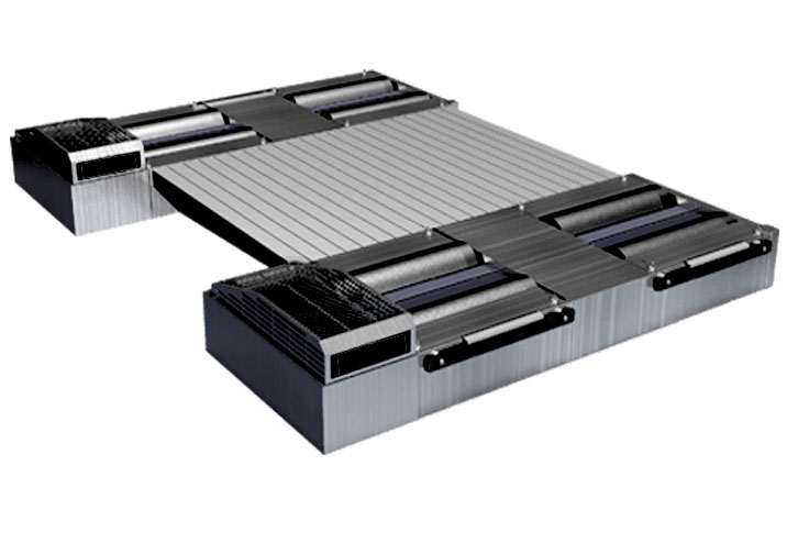
Features:
- Featuring high-power air-cooled eddy current absorbers and precision sensors to ensure stable and accurate testing with low maintenance costs;
- The test bed utilizes an integrated frame structure with precision-machined rollers for high balancing accuracy. The roller surface employs special treatment for high adhesion coefficient, coupled with high-strength bearings for superior load capacity and safety;
- With optimized structure design, low internal power loss, accurate basic inertia, and comprehensive safety devices to ensure secure and stable testing procedures;
- Fully complies with all applicable China national standards and technical requirements for chassis dynamometers;
- Compatible with steady-state test (ASM), transient test (VMAS), and loaded mode (Lug-down) testing methodologies;
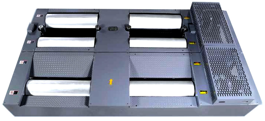
Working principle of Chassis Dynamometer
The driving wheels of the vehicle drive the main and auxiliary rollers to rotate. In the absence of slippage on the tire and roller surfaces, the linear speed on the roller surface is the driving speed of the vehicle. The speed sensor installed on the active roller outputs a pulse signal, and the pulse frequency is proportional to the roller speed.
The road resistance during driving is simulated by eddy current loading, and the translational inertia of the vehicle and the rotational inertia of non-driving wheels are simulated by the flywheel inertia system.
When the excitation current of the eddy current machine interacts with the rotating external magnetic field, a braking torque is generated, which reacts on the surface of the roller and acts on the S-shaped pressure sensor through the force arm. The output analog signal of the sensor is proportional to the magnitude of the braking torque.
According to relevant physical theorems, the power P can be calculated with the vehicle speed (speed) and traction force (torque).
How to Works Eddy Current..?
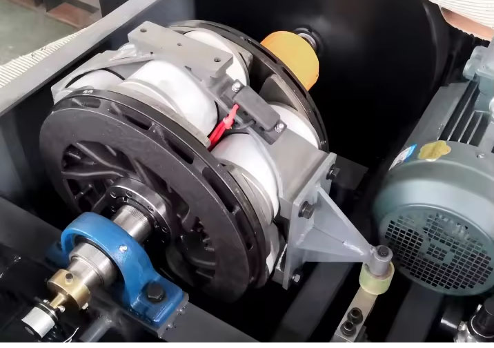
In a Chassis Dynamometer, the Eddy Current brake - or PAU - Power Absorption Unit is the device that actually loads the vehicle to simulate road. It's not an inertia dyno that just lets rollers spin. It's a load-controlled dyno.
It works on electromagnetic induction:
- Rotor + Stator: Inside the PAU you have a rotor made of conductive material like copper or aluminum, directly coupled to the dyno's rollers. Around it is a stator with electromagnets.
- Inducing Eddy Currents: When the vehicle's wheels spin the rollers, the rotor spins inside the magnetic field. This induces circulating currents - called eddy currents - inside the rotor.
- Braking Force: Those eddy currents create their own opposing magnetic field. The interaction produces a counter-torque that opposes rotation. That counter-torque is your braking load.
- Control: The load is controlled electronically. More current to the stator coils = stronger magnetic field = more eddy current = more braking force. Less current = less load.
The mechanical energy from the wheels is converted into heat in the rotor, which is then dissipated by air fans or water cooling. The system measures the reaction torque on the stator with a torque transducer and roller speed with an encoder, then calculates: Power (W) = Torque (Nm) × Angular Velocity (rad/s).
Characteristics:
- The chassis dynamometer is welded with square steel pipes and high-quality carbon steel plates, with a sturdy structure and high strength.
- The surface of the roller is treated with special technology, with high adhesion coefficient and good wear resistance;
- A high-power air-cooled eddy current power absorption device is adopted, with superior performance and easy installation;
- The measurement components use high-precision encoders and force sensors, which can obtain precise and accurate data;
- The signal connection interface adopts an aviation plug design, which ensures fast and efficient installation and stable and reliable data;
- The rollers are highly precise in dynamic balancing and runs smoothly.